Digital Command and Control, or DCC, suits
large layouts, the huge masterpieces that typically get photographed
in Model Railroader Magazine by
Kalmbach.
However, small layouts, like those in
Carl Arendt's site and made by
your humble author, work better with plain old "analog" controllers.
Even now in the 21st century,
DCC is barely becoming available in Z-scale, and it is not too often
worthwhile even on G-scale layouts, as the complexity is low
and there is often no need for multiple locomotives operating at once.
I have been designing "analog" controllers for thirty years.
My latest analog controllers are in fact digital on the inside,
but still they provide "plain old dc current", and are analog in spirit,
though digital in performance.
Every one I designed seemed like the ultimate, yet better came
along, again and again.
You can buy loads of different controllers, you can find lots of
articles in magazines and web pages on designs people swear to be
superior.
This article will tell you more than you wanted to know about
the differences.
First, let us discuss the types available, then I will provide
measured examples of several designs.
DC train controllers come in two basic types: Ones that try to fix the
speed of the train, and ones that fix the DC level from the controller.
How Conventional, Fixed-dc Controllers Work
Fixed output controllers, for want of a name, are the basic and original
type. They try to produce a constant output, usually voltage.
This is easily the best simple approach.
Before the advent of solid-state electronics, these controllers
were autotransformers, effectively just a transformer and a rectifier.
The control knob set the voltage, and the controller had as small
an output impedance as possible.
 The circuit at right explains the situation.
The controller provides a voltage (V), the motor's back-EMF is
a voltage (M), and there are three sources of resistance
between the two, that of the controller, that of the track and
wires, and that of the motor. The smaller the resistors,
the closer you get to the controller's voltage setting the
motor speed.
Sadly, cheaper controllers have high resistance (Rs),
long rails or thin wires increase the trackage resistance (Rt)
and smaller motors have larger resistance (Rm). The latter
is hard to avoid in small scales.
The circuit at right explains the situation.
The controller provides a voltage (V), the motor's back-EMF is
a voltage (M), and there are three sources of resistance
between the two, that of the controller, that of the track and
wires, and that of the motor. The smaller the resistors,
the closer you get to the controller's voltage setting the
motor speed.
Sadly, cheaper controllers have high resistance (Rs),
long rails or thin wires increase the trackage resistance (Rt)
and smaller motors have larger resistance (Rm). The latter
is hard to avoid in small scales.
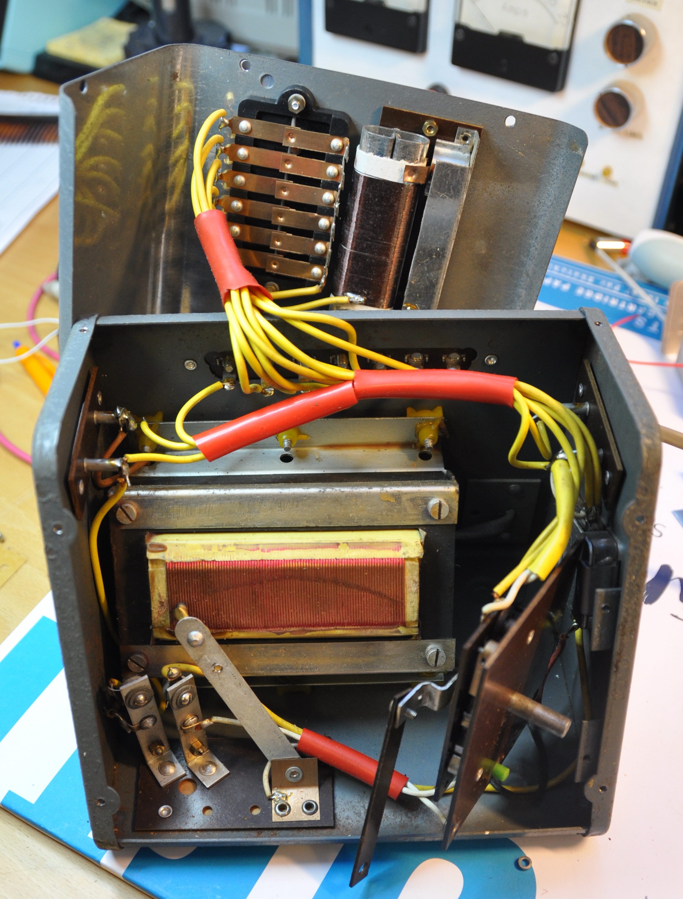
One of the best controllers made in the 1960s was a series out of
the UK from the "Hammant & Morgan" company, the H&M Powermaster.
I owned a Powermaster (a US model is pictured), and it served me well for many, many years.
These were pretty much just heavily-made autotransformers with (in those days) selenium rectifiers.
The front is shown below, the insides at right. The panel and knob shaft have been swung out
of the way to show the autotransformer. Note the wiper (the arm that moves it has been disconnected
for illustrative purposes) and the two thermal cutouts attached to the insulating
panel at the front of the chassis at the left.
The design is enduring if simple; a Playmobil set I bought for one of my kids
I believe to have a similar design, vintage 1999.

 There are controllers that have a rheostat instead of an autotransformer,
meaning that they change Rs in the circuit above instead of the voltage, V.
These are nasty: They slow the train by reducing the control exerted
by the controller. Tolerable for slotcars, where the driver must have fast
reactions, but bad for trains.
The Clipper by H&M was one such, as was the Duette.
This is one of the more recent, rheostat-based Duette models, lovely look,
bad electrical performance.
There are controllers that have a rheostat instead of an autotransformer,
meaning that they change Rs in the circuit above instead of the voltage, V.
These are nasty: They slow the train by reducing the control exerted
by the controller. Tolerable for slotcars, where the driver must have fast
reactions, but bad for trains.
The Clipper by H&M was one such, as was the Duette.
This is one of the more recent, rheostat-based Duette models, lovely look,
bad electrical performance.
Below is one of the older model Duettes.

Current-control

There is an esoteric type of controller---I designed the
dual-channel ETI-1508
pictured above in the 1980s---that
puts out constant current instead of voltage.
This produces constant torque in the motor.
This makes it hard to drive, but theoretically more realistic.
This is closer to what a real locomotive motor produces,
a constant force for constant throttle.
The problem is that this does not translate well to the
small scale of models; in a real train the mass is so huge
that speed changes slowly, and the driver responds with
throttle changes. In a model, it can all be over too quickly.
One of my electronic controllers is housed in the shell of an H&M Clipper.
It offers pure voltage and a "high-resistance" mode where it acts more like
a current-control system. Click
here for details.
A Note on User Interface
The H&M controllers and my Playmobil controller have the knob
arranged so that turning it one way sends the train in one direction,
turning the knob in the other direction sends the train in the other direction.
Forward one way, reverse the other.
Conversely,
many controllers (as will be seen below) control direction
by means of a switch. This is more like a real train,
or it would be if gears were simulated as well.
Matters such as these---how the box operates---are questions
of "User Interface" or "UI". Is one better? Sometimes yes, but in
this instance it may be a matter of personal preference.
A second UI property of interest is "inertia".
Some controllers deliberately delay effecting a change in
the throttle. This is an attempt to simulate the great
weight (inertia) of real trains.
Is this good, does it make driving the train a better
experience? How realistic is it, on one scale or another?
To an extent this is another matter or personal preference,
but it is clear that different amounts of inertia
will be required to achieve realism or convenience,
depending upon the scale and compression of the layout.
How Speed-Regulating Controllers Work
Model train motors are small, permanent-magnet motors
with brush commutators. This kind of engine has
a very useful property: it acts equally well as a
generator as a motor (ignoring minor losses). In practice, this means
that if it is being driven with a pulsed (or otherwise
varying) electrical signal,
in the moments between voltage being applied by the controller,
the motor is acting as a generator, and it produces a voltage.
This voltage is the so-called ``back EMF'' of the motor (Vm above),
and it is proportional to the speed of rotation of the motor shaft.
Feedback contollers measure the speed using the back EMF,
and try to adjust their operation moment by moment to maintain constant
speed in the motor. This is the basic principle of industrial
control, applied to motor speed.
When operating properly, the controller ensures that the
setting you have on your control knob is the speed of the
train, not the amount of power applied, as in the case of, say,
the accelerator pedal of your car. The controller acts like a
kind of cruise control.
A cruise control makes it easy to drive on the freeway. The feedback
controller makes the drivers life easier by keeping a train running at a
known speed, even as it climbs hills.
However, a cruise control is not useful for low-speed work... not much
call for shunting with an automobile. Why then, is a feedback controller
so popular for shunting?
The answer lies in the fact that when you scale things down and make
a four-inch model act like a 40' locomotive, it goes wrong. There
is very little weight in a model compared to the original, different
wind resistance, very different running friction and wheel slippage, yet
vastly more stiction, and very little immunity to small pieces of dirt
on the track, etc. Feedback controllers, and particularly the
PWM type, help to negate the nastier of these.
(The PWM action introduces frequency components that help
overcome stiction.)
Low-speed running is vastly improved in a feedback controller.
Pulse Control and Motor Heating
Many enthusiasts believe that pulse controllers overheat locomotives
and are responsible for burnouts and excessive brush and
commutator wear.
On the other hand, some authors have suggested that PWM controllers do not
increase the stress on motors significantly.
Who is right?
Theory aside, there is no doubt that motors run much hotter when driven by a PWM
controller. A 10 minute comparison test will show this clearly without
any more accurate measurements than the temperature sensing of your upper lip.
However, such tests also make it hard to believe that the heating could be
bad enough to burn out a locomotive. The excess heating is less pronounced
at higher speeds (actually at levels closer to 100% duty cycle of the
controller, meaning with its control turned up higher).
Thus the overheating situation with a pulsed controller
is worse if you are using a controller designed for
higher voltages than your loco requires, for instance running a Z-scale
locomotive with a PWM controller designed to handle G-scale models.
This penalty associated with mismatch of motor and controller does
not occur with non-pulsed controllers, and may account for evil
tales told about PWM designs!
Simple theory based on resistive losses says that the heat generated
with pulsed drive will be higher than the constant-dc case by a
factor of the duty cycle. In other words, if the PWM must use a 50%
duty cycle to achieve the desired speed, resistive losses will be double
what they would have been with a proportional analog controller, and if
it has to use a 10% duty cycle, the losses will be 10 times greater.
In practice, a small locomotive, N-scale say, will run fast with 11 volts
applied, and might shunt with 4 volts
applied. If a PWM controller applies 15 volts peak, it will run a duty
cycle of between 20% and 75%, worsening losses by anything from
one third to five times.
Note that the 5 times loss only occurs when the power delivered
to the locomotive is less than one-tenth of its full-power
load, so that it still represents half the power dissipation
of full load.
On this basis one might feel safe to disregard the additional
dissipation of a PWM controller: It can be no worse than running
at a large fraction of full speed for the same amount of time.
However, the ``resistive loss'' case discussed above is somewhat naive.
In fact, motors are quite complex magnetic systems. They present
inductive reactance and exhibit magnetic loss mechanisms
(such as eddy-currents in the armature metal).
Together with a PWM signal, these decrease efficiency and
cause heating of the motor. Worse, cooling is usually greater
when the engine RPM is high, but PWM losses are greater at low speed.
This makes for the unintuitive case that burnout is more likely at low
speed with PWM drive.
Much of the energy in a pulsed signal is contained in frequencies
above dc. A squarewave signal corresponding to PWM with 50% duty cycle
puts half of its energy into frequencies above dc; this fraction
increases as the duty cycle falls, as does the content at higher
harmonics of the pulse frequency.
This is roughly like trying to run your dc model with half of the
energy applied as ac power instead!
Above a certain frequency of operation, perhaps as low as a few hundred
Hertz, the energy is simply lost as eddy current losses in the magnetic
circuit.
Efficiency would be improved if the frequency of operation, the
pulse repetition rate or PRR, was to be lowered. However, below a few
tens of Hertz the locomotive vibrates.
This high-frequency loss accounts for much of the excess heating
in a locomotive driven with PWM.
A rule of thumb for electric motors is that their life is halved for
every 10C (18 degrees F) rise in the armature temperature. If your locomotive feels
warm to the touch on the outside, this suggests an external temperature
in the region of 38C/100F. (Luke warm is 38C or 100F, the limit of what you
can touch comfortably is in the region of 55C or 130F.) The armature
temperature could be much higher, perhaps 80C/175F, especially in light of the
fact that locomotives do not generally have a cooling fan on the drive
shaft, as do the motors of cordless power tools, for instance. Locomotive
motors tend to rely on having an open casing and a draft created
by the armature itself. This means that it is ``wearing
out''---approaching burnout---32 or 64 times faster than if you had left
it on the shelf. If that sounds scary, remember that shelf life
is very long, and the duty cycle of usage is usually quite low, unless
the locomotive is used somewhere like a shop window.
Motor heating can be reduced by having a waveform that is not
changing quickly. In fact, the rectified mains power, sinewave-like,
is a very good compromise between having pure, filtered dc,
and pulses that overcome stiction and allow measurement
of back EMF. Filtered (regulated) dc is
not an option with feedback controllers, because it does
not allow a moment now and then for the controller to measure
the back-EMF.
For the scientifically-inclined reader, I refer you to a paper published
in the professional literature:
Scott, J. B., McLeish, J. & Round, W. H. (2009).
Speed control with low armature loss for very small sensorless brushed DC motors.
IEEE Transactions on Industrial Electronics, 56(4), 1223-1229.
Some Controllers Reviewed
Let us now look at a number of commercial controllers.
 I mentioned a Playmobil transformer that
I suspect to be of the autotransformer type like the old H&M units.
This is it.
I mentioned a Playmobil transformer that
I suspect to be of the autotransformer type like the old H&M units.
This is it.


These pictures show the voltage waveform applied to a train on a test track.
The LHS image shows a single trace, recorded with the train at slow
speed. The RHS trace shows a number of waveforms at different speeds
stored on the oscilloscope screen.
The waveforms would look like full-wave rectified sinewaves except for
two things: The tops of the peaks are a bit flattened on account of
the output impedance of the transformer, and the waveform does
not fall to zero between peaks because of the back-EMF from the
locomotive. Note that increased throttle gives simply an
enlarged version of the previous case, with the back-EMF being
a bit higher and a bit noisier, from the motor's commutator.
The small yellow symbol next to the digit 1 on the RHS of the
screen shows the zero-voltage or ground level.
At shunting speeds this HO locomotive has a back-EMF of about 2V.
There are no surprises in the operation of this controller.
 Next we come to a Bachmann 6607 controller, as supplied with
a number of their starter sets. This controller intends to
be an autotransformer type, but it is built as a transformer with
a number of taps, between which the knob switches.
The best feature of this is that it is cheap.
Unfortunately, the resistance of the controller is rather high,
because the unit is small and light, and yes, cheap.
Next we come to a Bachmann 6607 controller, as supplied with
a number of their starter sets. This controller intends to
be an autotransformer type, but it is built as a transformer with
a number of taps, between which the knob switches.
The best feature of this is that it is cheap.
Unfortunately, the resistance of the controller is rather high,
because the unit is small and light, and yes, cheap.
The low-speed regulation is not much of an issue, because the
lowest speed is not a crawl at all, more of a walk.
This is the worst unit I have ever tested.

There is nothing exciting about the waveforms from this controller; they
are substantially the same as the Playmobil, except that they reduce
more if you load the locomotive down.
 The Tomix controller pictured here was shipped with an N-gauge Thomas starter set.
It is essentially the same design strategy as the Bachmann 6607: It is a multitap
transformer, rated at 7VA max, with the knob running a complicated switching system
that changes taps and puts one or more diodes in series with the load to rectify and drop
voltage.
The Tomix controller pictured here was shipped with an N-gauge Thomas starter set.
It is essentially the same design strategy as the Bachmann 6607: It is a multitap
transformer, rated at 7VA max, with the knob running a complicated switching system
that changes taps and puts one or more diodes in series with the load to rectify and drop
voltage.
 The inside view says it all. There are 4 diodes under the PCB. Note the small
glass envelope that contains a bi-metallic strip overload cutout.
The inside view says it all. There are 4 diodes under the PCB. Note the small
glass envelope that contains a bi-metallic strip overload cutout.
 Lionel make a very similar basic unit, the 4660 Hobby Transformer.
Provided with a somewhat more robust case, it contains the same 7-tap transformer, same thermal
overload cutout, etc. Almost identical to the Bachmann on the outside.
Are all of these made in the same Chinese factory, or is there a lot of
plagiarism in the cheap controller business?
Lionel make a very similar basic unit, the 4660 Hobby Transformer.
Provided with a somewhat more robust case, it contains the same 7-tap transformer, same thermal
overload cutout, etc. Almost identical to the Bachmann on the outside.
Are all of these made in the same Chinese factory, or is there a lot of
plagiarism in the cheap controller business?
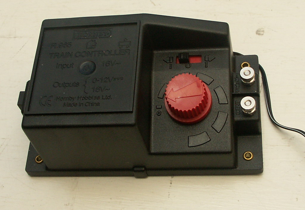 Next let us look at a Hornby R965 controller, as supplied with
Hornby starter sets. This controller is a completely different
thing.
Like the Gaugemaster,
it is a feedback type that uses a thyristor (or SCR) as
an electronic element switching a rectified but unfiltered source of dc,
at line frequency.
Next let us look at a Hornby R965 controller, as supplied with
Hornby starter sets. This controller is a completely different
thing.
Like the Gaugemaster,
it is a feedback type that uses a thyristor (or SCR) as
an electronic element switching a rectified but unfiltered source of dc,
at line frequency.
The low-speed shunting performance is spectacular.
Looking at the first waveform below, you can see that the pulse changes
from moment to moment, adjusting for the speed of the motor. If anything
the gain of the circuit is too high, and the control is just on the
edge of stability (it is overcompensating in the image).
If it has a fault it is that it can "drift" if it gets hot.
It is not unknown for the controller to have a minimum speed with
the knob fully down. It is lucky that it has an "off" position
on the reversing switch.


The waveforms show considerable filtering; there must be a decent capacitor
across the rails supressing both RF interference, and smoothing the
back-EMF waveform... notice the absence of the noise on the traces
that is visible on the Playmobil controller waveforms.
This is a good design if you know the scale of the locomotive (the
size of its motor), you have plenty to supply voltage, and less
concern about motor heating.
These two pictures of load voltage show the controller dynamically
changing its delivered power. In the RHS image, you can see it
switching from modest power on each half-cycle to double
power on alternate half-cycles. (The supply is 60Hz here.)
This is further evidence of high loop gain, plus interaction
of the 60Hz with the mass of the motor armature.
This is the best starter set controller I have seen to date.
 The Fleischmann 6720 is shipped with their analog starter sets.
The mechanical design is delightful inside, giving a very cheap,
very repairable, and yet very appealing controller.
Electronically it is a simple voltage source, but one with very
low output impedance. It uses an LM317 regulator IC and a
switched set of resistors. It is intended that it be powered from an
unregulated dc voltage supply, although it ought to operate from
an unfiltered one at a pinch. It supplies the regulation to give
a very good example of the conventional, fixed-dc controller described
above.
As such, it performs better than the Playmobil type, because
its output resistance is virtually zero.
The Fleischmann 6720 is shipped with their analog starter sets.
The mechanical design is delightful inside, giving a very cheap,
very repairable, and yet very appealing controller.
Electronically it is a simple voltage source, but one with very
low output impedance. It uses an LM317 regulator IC and a
switched set of resistors. It is intended that it be powered from an
unregulated dc voltage supply, although it ought to operate from
an unfiltered one at a pinch. It supplies the regulation to give
a very good example of the conventional, fixed-dc controller described
above.
As such, it performs better than the Playmobil type, because
its output resistance is virtually zero.
This gives the most smooth, most quiet model operation,
but there is no active feedback so that the shunting performance
depends upon the quality and cleanliness of track and loco.
(Of course, if you are buying Fleischmann track and locos you
are likely to get that quality, but but it comes at no small price.)
What is most surprising to this reviewer is that it is almost as
good as the feedback types, at least on the N-scale models for which
it is intended.
The waveforms are not worth reproducing... plain dc and a bit of noise.
 The Tech 4 controller is very impressive in appearance, and unusual in
its electronic action.
It is one of the models that offer inertia, with
braking via a button, plus it has an
override switch for the inertia, very useful if you want to
do a quick setup rather than drive for realism.
Unfortunately it will instantaneously reverse if you flick
the direction switch. It does however respond smoothly,
even with inertia (which it calls "momentum") switched off.
The Tech 4 controller is very impressive in appearance, and unusual in
its electronic action.
It is one of the models that offer inertia, with
braking via a button, plus it has an
override switch for the inertia, very useful if you want to
do a quick setup rather than drive for realism.
Unfortunately it will instantaneously reverse if you flick
the direction switch. It does however respond smoothly,
even with inertia (which it calls "momentum") switched off.
The drive signal consists of pulses whose width is NOT modulated,
separated by a dc level that increases with the throttle setting.
I assume that the pulses are there to help defeat stiction in models,
and the lower level there to control force.
The waveform images below show its action at various throttle settings.
In one sense it combines the worst of both worlds (pulses that increase dissipation
at low speed and no feedback) but it has an excellent interface, and the
action is better than an autotransfomer type.
This controller is popular, and is a triumph of UI.


 I have used a GaugeMaster for many years.
This is the classic design of thyristor-based, feedback train control.
Operation is similar to the Hornby unit above, but without the
drifts and bugs. The circuit, elegant and yet effective,
is shown below.
I have used a GaugeMaster for many years.
This is the classic design of thyristor-based, feedback train control.
Operation is similar to the Hornby unit above, but without the
drifts and bugs. The circuit, elegant and yet effective,
is shown below.
Low-speed operation is smooth and reliable. The unit
offers no bells and whistles, no inertia (very few units
offer both feedback and inertia), and yet it is quite
a satisfactory controller, especially for small layouts
and shunting yards.

Incidentally, the D13T1 (or any other) [Programmable] Unijunction Transistor (UJT or PUT) is now hard and expensive
to get (2019, but it's been hard for a few years now),
despite the fact that a UJT is nothing more than an inverse-polarity SCR, so PNPN instead of NPNP.
Two things you can do about this. The first circuit below replaces the UJT with a plain BJT, and works just like the
original. In noisy environments, put a 1nF cap in parallel with the 10k resistor.

Possibly a more useful variation is the "forward" version below. This circuit has the advantage that one of the
motor connections (rails) is ground.
As above, in noisy environments, put a 1nF cap in parallel with the 10k resistor.

 DIY kits for controllers employing basic feedback and
PWM are not uncommon. The controller here, from a design
that appeared in Silicon Chip magazine, produces
results that are typical of the genre.
DIY kits for controllers employing basic feedback and
PWM are not uncommon. The controller here, from a design
that appeared in Silicon Chip magazine, produces
results that are typical of the genre.
The waveforms show the operation. Output is a pulse of fixed
amplitude and varying width. In the first image, the output
voltage (controlled by the supply used with the pulser circuit)
is large, and the width small, corresponding to the worst
situation for engine heating. In the second image, a lower
supply is used (about 12V dc instead of rectified and
filtered 16VAC) so the pulse is smaller and thus wider. The
second image shows how the pulse varies as the throttle is
adjusted.
Note that the pulses are about 5ms apart; the controller uses a PRF
of about 200Hz. This makes for smoother operation, though
this exaserbates motor heating problems.
In contrast the Gaugemaster and other line-synchronised designs
run at 100 or 120Hz (for 50 or 60Hz supply frequencies).


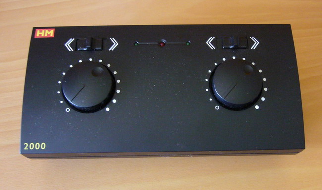 This is the up-market Hornby offering.
Labelled "HM", it is presumably trying to capitalise upon the
Hammant & Morgan reputation; it is designed to resemble
the Duette noted above, and controls two trains independently
as did the Duette.
This is the up-market Hornby offering.
Labelled "HM", it is presumably trying to capitalise upon the
Hammant & Morgan reputation; it is designed to resemble
the Duette noted above, and controls two trains independently
as did the Duette.
My only complaint is that the knobs are not center-off action,
like the Duette, but reverse is achieved using a slider switch.
The reverse is instantaneous if you flick the switch while the
train is running.
It is clear from observing the output waveforms below
that it is a thyristor-feedback design, like the Hornby basic R965 or Gaugemaster
feedback designs. The knob seems to have a somewhat nonlinear taper, so that low speeds are
easily achieved. It exhibits some of the heating characteristic
of a PWM design. It has a modest degree of feedback, less if anything than the
Gaugemaster series. Otherwise it is largely comparable to the
Gaugemaster units in performance.

 This is a small controller marketed by Thektronics for use with
Z-scale models. It is a PWM design without feedback, producing
a pulse drive waveform with duty cycle fixed by the position of
the potentiometer.
This is a small controller marketed by Thektronics for use with
Z-scale models. It is a PWM design without feedback, producing
a pulse drive waveform with duty cycle fixed by the position of
the potentiometer.
It works relatively well, provided its supply voltage is as advertised,
or the battery inside is in good condition. As advertised it does a good job
of low-speed shunting, in comparison with the Marklin controllers.
It runs close to 60Hz.
However, it makes no attempt to set speed, so if you run the
train at a constant setting for any time, more than 30 minutes
for example, the loco will not "stick", but it is likely to double
or halve in speed. This makes it excellent for small end-to-end
layouts, but you would not use it with a loop in a store window.

 Here is the prototype of one of my own PWM designs.
It is vintage April 2006, click
here for details.
The output waveform of this contoller is a slew-limited triangle
up to modest throttle, then a trapezoid with a 125Hz PRF. This minimises heating,
but allows very tight feedback control. The controller
has adjustable inertia and braking (that can be bypassed with a front-panel switch),
both centre-off and reverse-by-switch modes of operation,
and it prevents sudden reversal by automating reverse selection.
It has a "check engine" light to indicate a variety of faults, too.
Here is the prototype of one of my own PWM designs.
It is vintage April 2006, click
here for details.
The output waveform of this contoller is a slew-limited triangle
up to modest throttle, then a trapezoid with a 125Hz PRF. This minimises heating,
but allows very tight feedback control. The controller
has adjustable inertia and braking (that can be bypassed with a front-panel switch),
both centre-off and reverse-by-switch modes of operation,
and it prevents sudden reversal by automating reverse selection.
It has a "check engine" light to indicate a variety of faults, too.
Waveforms are shown below.
The noise on the engine back EMF, clearly visible in the RH image
after the inductive flyback, is digitally filtered by the controller CPU.


 In 2011 I bought a Hornby "Night Mail" starter set, recalling the marvellous fun I had
with the mail coach I had as a kid. It came with a new design of controller.
In 2011 I bought a Hornby "Night Mail" starter set, recalling the marvellous fun I had
with the mail coach I had as a kid. It came with a new design of controller.
The most obvious brilliant advance is that the reverse switch is
mechanically interlocked with the speed control knob so that it is not
possible to reverse direction except at zero thrust. With hindsight
this is simple and effective, a brilliant advance. (We have only been
making these things for 40 years without anyone thinking of this!)
Electronically it is not elegant, however. It uses rectified and filtered dc, and at 19V
it is much higher than the maximum required output of 12V. The system is a straightforward
PWM squarewave, with no feedback,
whose duty cycle varies from 0 to about 75%, so it works effectively but is
not gentle on the motor. It is implemented with a quad-opamp IC, giving good overload
control but not much else to recommend it.
The PCB is a single-sided affair, not layed out particularly efficiently.
The electronic side of the design is not overly smart, but it must be cheap to manufacture, and easy to
deploy world-wide, as it uses a plug-pack.
If one could collect up the ideas above, the interlocked reverse switch of the Hornby
or alternatively the center-off knob of the Playmobil/Fleischmann,
the simplicity/performance of the Gaugemaster,
and the switched inertia of the Tech,
would together make a very neat yet low-cost unit,
easy to use and able to do most things you need.