This layout is based loosely on the "Woodland Scenic" N-scale
demonstration kit.
That kit is designed to use Atlas N-scale track and to be
3'x5' in size.
The original may have been designed as a great vehicle for
Woodland Scenic's products, but it was not very well designed
either from the point of view of track geometry,
or in terms of efficient use of space, or in terms of
railroading pleasure!
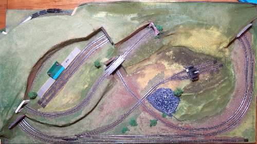
The Atlas track kit was modified by Atlas to better fit the claimed
Woodland Scenic geometry, and I have further changed it to reduce the total size and
improve the fit of the tracks, and to add a few extra sidings for
more enjoyment. The new track plan, as produced by the
Atlas Planning Freeware (RTS5.0), appears here.
Note that the grid shows 1-foot squares, and the original intended
size is the size of the diagram, although the final design fits
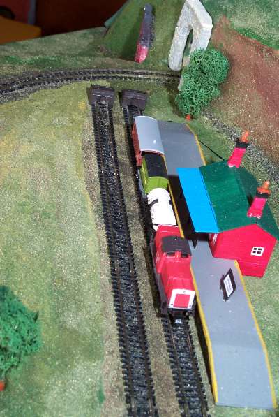
on a 2.5 by 4.5-foot baseboard. The two sidings in the middle-left
area and the double siding in middle-right are both added, the
former to service a rural mountain station, the latter a quarry.
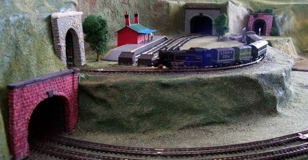
The layout from above.
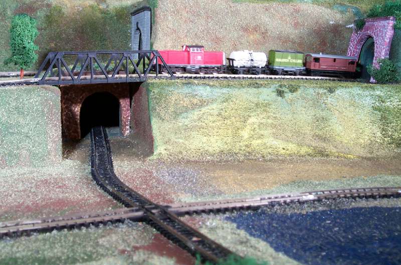
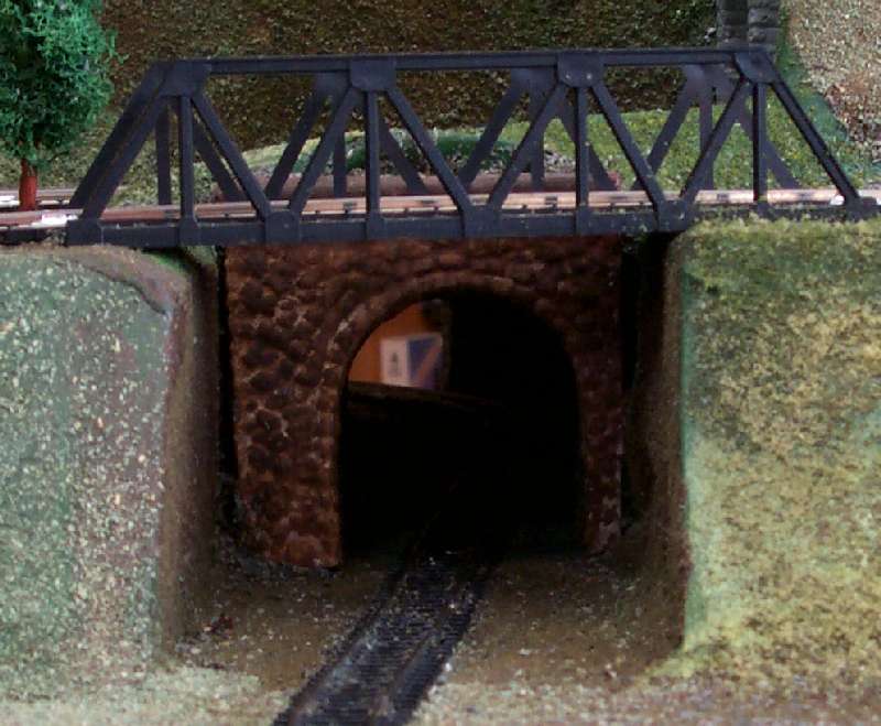
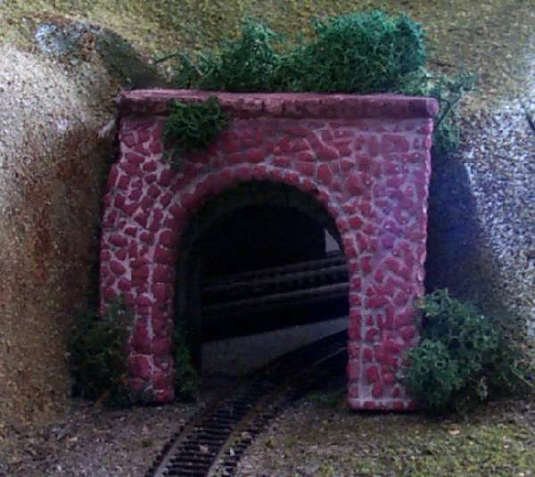
The finished layout derives a great deal of interest from the use of tunnels;
note that three of the five switches are inside tunnels.
Comparison of this photo with the plan shows what parts are enclosed and
what parts exposed.
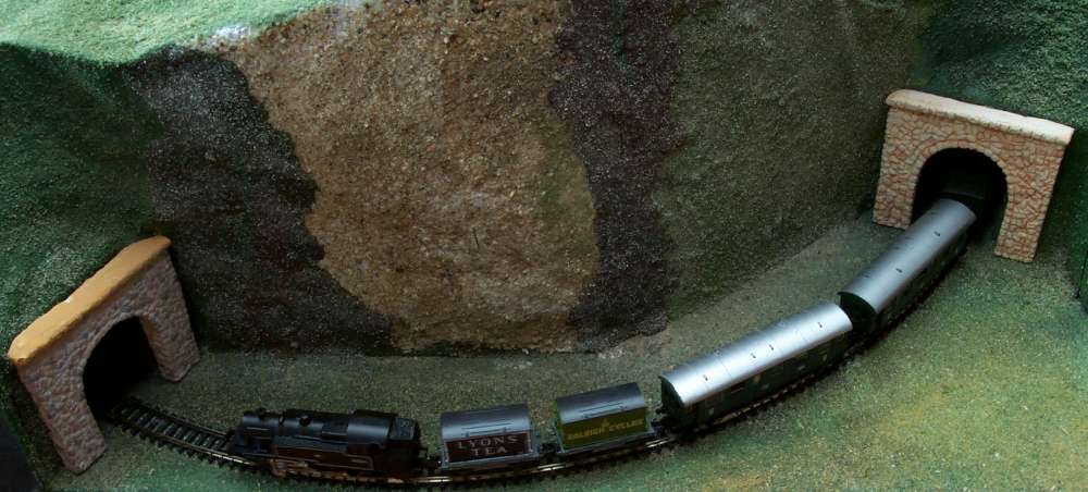
The layout in a perspective view.
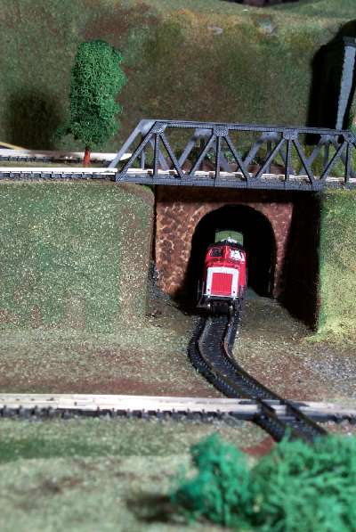
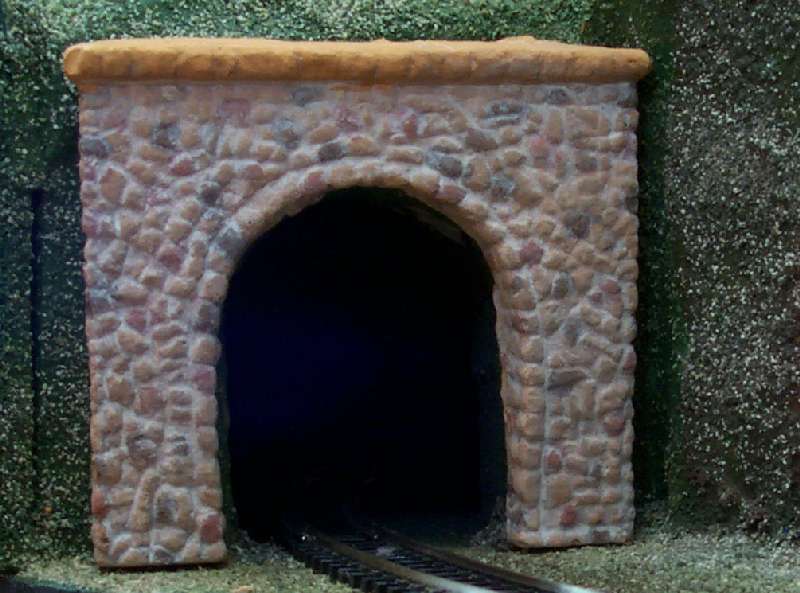
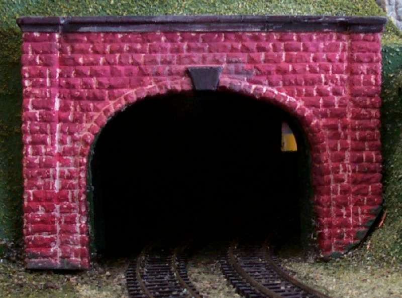
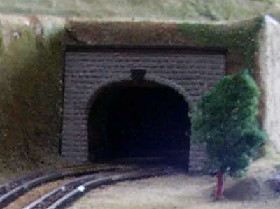
As noted, the layout derives a great deal of interest from the use of tunnels;
There are now eight rather than four tunnel portals, three of them
being double-width.
(Yes, the last tunnel's "crack" is deliberate!)
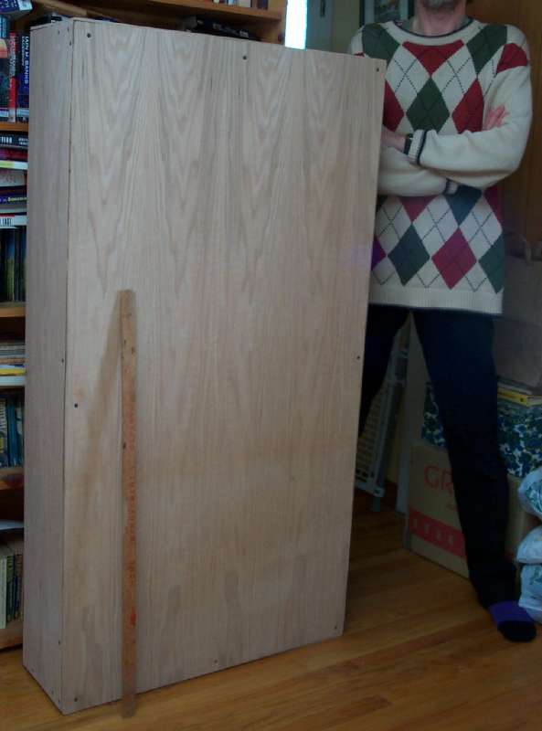
Now this layout was designed to be "portable", meaning that it packs up into a
"manageable" box when the top is attached. By "portable" and "manageable"
I mean it is about 56x30x9 inches. One person can lift,
carry and unpack it, but it is sadly too big to be shipped UPS.
The photo shows the layout with cover fitted, next to a six-foot-tall
person, and with a yard rule, for scale.
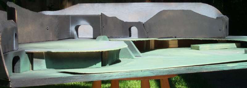
For strength and durability the basic structure is painted wood,
as shown in the adjacent photograph taken at an early stage
of construction.
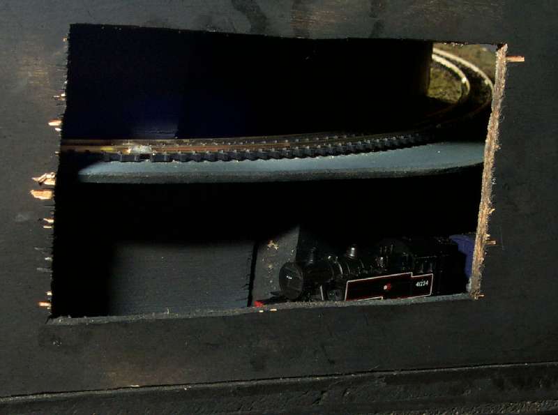
The tunnels are provided with access holes to allow switching of the turnouts
as well as cleaning, maintenance and crash recovery. There are two
ports on the back and one in the end.
These pictures shows the access holes.
The wires visible in the picture of the rear access holes permit connection
of a controller to the track to power the trains.
 The Atlas track kit was modified by Atlas to better fit the claimed
Woodland Scenic geometry, and I have further changed it to reduce the total size and
improve the fit of the tracks, and to add a few extra sidings for
more enjoyment. The new track plan, as produced by the
Atlas Planning Freeware (RTS5.0), appears here.
The Atlas track kit was modified by Atlas to better fit the claimed
Woodland Scenic geometry, and I have further changed it to reduce the total size and
improve the fit of the tracks, and to add a few extra sidings for
more enjoyment. The new track plan, as produced by the
Atlas Planning Freeware (RTS5.0), appears here.
 The layout from above.
 The layout in a perspective view.
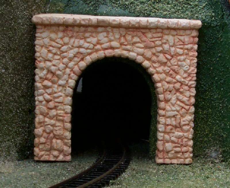


 Now this layout was designed to be "portable", meaning that it packs up into a
"manageable" box when the top is attached. By "portable" and "manageable"
I mean it is about 56x30x9 inches. One person can lift,
carry and unpack it, but it is sadly too big to be shipped UPS.
The photo shows the layout with cover fitted, next to a six-foot-tall
person, and with a yard rule, for scale.
Now this layout was designed to be "portable", meaning that it packs up into a
"manageable" box when the top is attached. By "portable" and "manageable"
I mean it is about 56x30x9 inches. One person can lift,
carry and unpack it, but it is sadly too big to be shipped UPS.
The photo shows the layout with cover fitted, next to a six-foot-tall
person, and with a yard rule, for scale.
 For strength and durability the basic structure is painted wood,
as shown in the adjacent photograph taken at an early stage
of construction.
For strength and durability the basic structure is painted wood,
as shown in the adjacent photograph taken at an early stage
of construction.
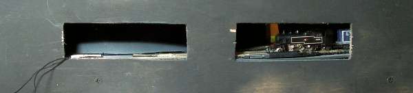 The tunnels are provided with access holes to allow switching of the turnouts
as well as cleaning, maintenance and crash recovery. There are two
ports on the back and one in the end.
These pictures shows the access holes.
The tunnels are provided with access holes to allow switching of the turnouts
as well as cleaning, maintenance and crash recovery. There are two
ports on the back and one in the end.
These pictures shows the access holes.