This page is as much a description of a layout as it is an expose and
review of the Fleischmann N-scale rack-rail system.
May it be useful to you.
This layout proved to require considerably more effort than I
anticipated, especially for a layout consisting of a single 50"
run of almost-straight track.
There was many a twist in that "almost".
The History
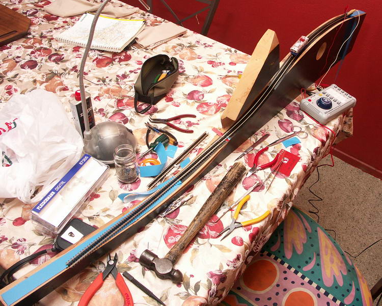
 In the foreground you see the old benchtop from the Physics lab that was
renovated in Christmas 2006.
When Bruce and I saw these marvellous pieces of wood in the dumpster we
grabbed them. New Zealand Rimu,
at once I knew the stuff should be recycled in some beautiful and
exciting way. Back in California I had an idea for a wall-hangable layout
using the Fleischmann N-scale cog track and locomotive. Here was
just the material for this job: Beautiful wood that was thicker than an N-scale
layout needs to be wide.
In the foreground you see the old benchtop from the Physics lab that was
renovated in Christmas 2006.
When Bruce and I saw these marvellous pieces of wood in the dumpster we
grabbed them. New Zealand Rimu,
at once I knew the stuff should be recycled in some beautiful and
exciting way. Back in California I had an idea for a wall-hangable layout
using the Fleischmann N-scale cog track and locomotive. Here was
just the material for this job: Beautiful wood that was thicker than an N-scale
layout needs to be wide.
 This is the woodwork part of the first version of the layout.
The route up the mountain is the edge of the frontmost
piece. The two routed recesses at either end will become
stations.
The idea is that the grainy Rimu wood represents rock,
the rock of a mountain, up the side of which a cog railway will
snake.
This is the woodwork part of the first version of the layout.
The route up the mountain is the edge of the frontmost
piece. The two routed recesses at either end will become
stations.
The idea is that the grainy Rimu wood represents rock,
the rock of a mountain, up the side of which a cog railway will
snake.
The layout was partly inspired by discovering the
rack railway system from my favourite N-scale maker, Fleischmann,
partly by the sight of the thick lab-bench wood,
and partly by a postcard that Dominique sent to us years ago.
This post card showed a number of European trains,
including the Pilatusbahn.
There are other cog railways such as one climbing Snowdonia in Wales
(http://www.snowdonrailway.co.uk/),
and Mount Washington in New Hampshire
(http://www.thecog.com/),
but the Pilatusbahn seems to be the epitomy.
There is a good potted history of cog rail at
http://www.cograilway.com/history.htm.
Note in the picture above the two electronic
signalling boxes, one at the entrance to each station,
are already built into the "rock". These are
GP2A25 Electro-optic proximity sensors for the automatic controller,
but they are about the size of a trackside signal when viewed in
N-scale.
The circular hole leads to a small control panel to activate the layout.
The layout is intended to be hung on a wall, just like a picture.
The train will periodically leave one station and climb or descend to the
other.
The Problems
I started writing this page in August 2007, as I tackled version 2 of the
layout.
Updates continue as I learn more about using the Fleischmann 87305, 9119 Rack Rail
and friends.
I am not sure if I will ever finish the layout, indeed I am sure it will never be
reliable enough to run without regular operator intention. Below is the
saga and the knowledge I have acquired about the whole N-scale funicular
system. It is a pity, as it looks awfully impressive.
Around February 2009, Fleischmann went into receivership and was bought by the
company that previously bought Roco and turned that company profitable.
The blogs intimate that it should have been no surprise, as their technology
had not matured as did other manufacturers, for example my brand new
loco pictured here is still a 3-pole design, and I gather all Fleischmann
locos remain so.
The Fleischmann cog system is supposed to be able to climb up to
a 30% grade grade. I dutifully designed the route with a maximum grade of
30% grade.
 This is the Fleischmann 9119 Rack Rail.
Unlike the regular Fleischmann N-scale track, the rack rail
is not made with ballast formed into the plastic base
of the track, but resembles the common Peco flextrack and settrack
arrangement with individual sleepers (ties). It is the higher
profile type of track, and the rails do not like to deform when bent,
making it hard to manage.
This is the Fleischmann 9119 Rack Rail.
Unlike the regular Fleischmann N-scale track, the rack rail
is not made with ballast formed into the plastic base
of the track, but resembles the common Peco flextrack and settrack
arrangement with individual sleepers (ties). It is the higher
profile type of track, and the rails do not like to deform when bent,
making it hard to manage.
Note also the frequent holes placed to accomodate nails to hold the
track in place.
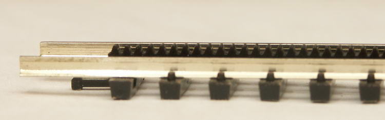 The sleepers are held together by the toothed rack in the middle
of the track. This protrudes above the rails and is engaged
by a cog on the axle of one pair of drive wheels in the
locomotive.
The sleepers are held together by the toothed rack in the middle
of the track. This protrudes above the rails and is engaged
by a cog on the axle of one pair of drive wheels in the
locomotive.
The first problem is that the rails have a tendency to buckle.
They bend around corners left and right just fine, but not in the other direction.
When trying to make them conform to the curvature of hills, they tend to spring
out of the plastic retainers on the sleepers/ties, damaging them.
The second problem is that the rail needs to be nailed in a lot of places,
for which it has numerous holes. However, when you have the nails in deep enough,
the rack is no longer flat, and it dips compared to the rails where the
nails are located.
The dips in the rack and the irregularity of the rails are not a problem,
except when you approach 30%, before which grade the slightest
imperfection leads to the cog letting go and the locomotive slithering
and juddering to a gruesome crash at the bottom of the hill.
 The third problem concerns not the grade, but the rate at which
the track can transition from one grade to another.
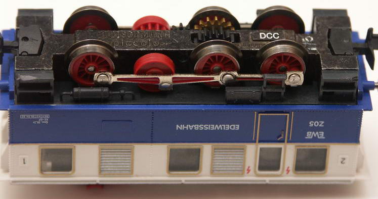
This is an underside view of the Fleischmann Edelweiss Cog Locomotive,
an 87305.
Note that it is a six-wheel arrangement, and that the cog that
engages the rack is on the middle of the three axles.
This is, I believe, a design flaw.
When the track curves in a convex fashion, there is a tendency to lift
one or both of the end axles off the rail, leaving the loco see-sawing.
Worse, a concave curvature lifts the axle with the cog, and the
loco is vastly more likely to let go and slide down.
It would function much better as a four-wheel design (perhaps like those
0-6-0 steam locomotives whose middle axle is largely cosmetic).
The third problem concerns not the grade, but the rate at which
the track can transition from one grade to another.
This is an underside view of the Fleischmann Edelweiss Cog Locomotive,
an 87305.
Note that it is a six-wheel arrangement, and that the cog that
engages the rack is on the middle of the three axles.
This is, I believe, a design flaw.
When the track curves in a convex fashion, there is a tendency to lift
one or both of the end axles off the rail, leaving the loco see-sawing.
Worse, a concave curvature lifts the axle with the cog, and the
loco is vastly more likely to let go and slide down.
It would function much better as a four-wheel design (perhaps like those
0-6-0 steam locomotives whose middle axle is largely cosmetic).
I was forced to rework the wood to reduce the radius of curvature
at both convex and concave locations. I scrapped much of the
track. I also devised a better method for attaching the
track to the wood base, dispensing with nails altogether.
The Second Version
 This is the track half, viewed from the mountain side, after a rework
to reduce the radii of curvature. The most visible change is the use of
double-sided tape to mount the track. This proved to give much
less undulation in the rails.
This is the track half, viewed from the mountain side, after a rework
to reduce the radii of curvature. The most visible change is the use of
double-sided tape to mount the track. This proved to give much
less undulation in the rails.
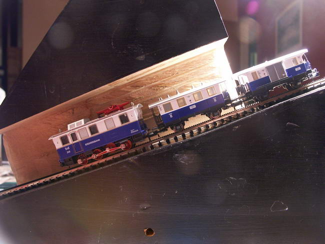 Just to give some idea of the steepness of the railway, this is a
picture taken with the camera horizontal. You are looking at the whole train
from within the cutaway mountain, and it is climbing out of the tunnel
towards the top station. The black faces mate with the other half of
the structure to complete the tunnel.
Just to give some idea of the steepness of the railway, this is a
picture taken with the camera horizontal. You are looking at the whole train
from within the cutaway mountain, and it is climbing out of the tunnel
towards the top station. The black faces mate with the other half of
the structure to complete the tunnel.
 This closeup shows a section of track with a serious "bump"
in the near-side rail. The pins have been added to press the
bump down into the correct arc.
This may not seem like much, but it is enough to lift the
wheels on one side and stop the train. A concave, rather than convex,
bump, makes it let go and slide down.
This closeup shows a section of track with a serious "bump"
in the near-side rail. The pins have been added to press the
bump down into the correct arc.
This may not seem like much, but it is enough to lift the
wheels on one side and stop the train. A concave, rather than convex,
bump, makes it let go and slide down.
If you can see no error in the arc, compare the height
of the near-side rail with the height of the rack. In the
vicinity of the nail, note that the apparent height of the
teeth of the rack above the line of the top of the rail is
somewhat reduced. This undulation can barely be felt
by running your finger along the track quickly, while wearing
surgical gloves to reduce the sensation of roughness, but
it causes a perceptible roll in the motion of the loco.
 Bending the rails absolutely demands a rail bender. The use of
a rail bender at such scales is virtually unheard-of, since
modern track flexes relatively easily in the X-Y plane,
but in the Y-Z plane it is another story altogether.
Bending the rails absolutely demands a rail bender. The use of
a rail bender at such scales is virtually unheard-of, since
modern track flexes relatively easily in the X-Y plane,
but in the Y-Z plane it is another story altogether.
Here is a rail bender fashioned from the bearings of an old
disk drive and some aluminium and steel plates and bolts.
Thanks to Brian Clark, workshop master. The
main plate is 45mm by 35mm.
Experience from Elsewhere
September 2009 saw me complete work on
Sprocket BahN,
another layout based on the same Fleischmann rack
rail system.
That layout is reasonably reliable, but will not run for days and days
without intervention, as one might hope for a layout that is fully
automated and expected to keep a timetable.
In the course of Sprocket BahN I hoped to sidestep all the problems
described above. I encountered yet another one: The cog meshing with
the rack converts force along the line of the track into a lifting force
that almost overpowers the weight from the steel masses in the
locomotive, resulting in the loco having greatly increased sensitivity
to small particles or discontinuities on the track. It regularly
loses electrical contact with one or other rail and "sticks".
On any given track there will be a speed setting that gives the loco
enough momentum to trundle over the discontinuities. The upshot
is that you have to run faster than you might like to make it
through the difficult parts, especially the concave regions
where the second derivative of height (the rate of change
of gradient) is largest.
--- there may be even more to come ---
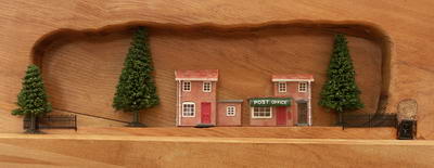
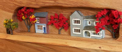
The Layout Itself
Here are the Top and Bottom stations before the track is laid.
The buildings are from the Hornby Lyddle End range, but they have
been sawn to yield "relief" fronts (like something from
Portmeirion).